Integration of FAM on Gazebo
This tutorial describes how the Force Allocation Module (FAM) is integrated in Gazebo via a ModelPlugin.
1. What is FAM?
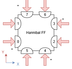
FAM is the module that maps the desired overall force and torque acting on a free-flyer to the individual thrust forces required at each propeller. This allows a high-level controller to command abstract movements (like “move forward” or “rotate”) while the FAM handles the specific hardware actuation.
Mathematical Foundation
The relationship between desired forces and propeller thrust is defined by:
\[\mathbf{T} \cdot \mathbf{f}_{prop} = \mathbf{f}_{des}\]Definitions:
- $\mathbf{T} \in \mathbb{R}^{n_{des} \times n_{prop}}$: The Actuator Matrix, determined by the physical position and orientation of the propellers relative to the center of mass.
- $\mathbf{f}_{des}$: The Effort Vector, typically consisting of forces in $+x$ and $+y$ and torque in $+z$ for planar free-flyers.
- $\mathbf{f}_{prop}$: The Thrust Vector, representing the scalar thrust value for each individual propeller.
2. Solving for Individual Thrusts
In overdetermined systems (where there are more propellers than degrees of freedom), $\mathbf{T}$ cannot be directly inverted. Instead, we use the Moore-Penrose Pseudo-inverse ($\mathbf{T}^{+}$) to find the least-squares solution:
\[\mathbf{f}_{prop} = \mathbf{T}^{+} \cdot \mathbf{f}_{des}\]This approach distributes the load across all available thrusters efficiently.
3. Gazebo Plugin Implementation
The FAM logic is integrated into Gazebo by compiling the .cpp plugin file via CMakeLists.txt.
Implementation Workflow
- Initialization: The Actuator Matrix parameters are defined within the GNC (Guidance, Navigation, and Control) module and can be adjusted via external configuration files.
- Subscription: The plugin subscribes to a command topic (e.g.,
geometry_msgs/Wrench) to receive the desired effort vector $\mathbf{f}_{des}$. - Calculation: The GNC module computes the pseudo-inverse and matrix multiplication, then publishes the resulting $\mathbf{f}_{prop}$ values to the
/actuator_force_goaltopic. - Application: The thrust values are applied to the model using the Gazebo API.
Handling Force Direction
While AddForceAtRelativePosition applies force at a specific point, it does not automatically align the force vector with the robot’s changing orientation. To ensure the force is always exerted in the correct outward-facing direction, you must first retrieve the current world pose of the free-flyer.
Code Snippet (Example for 1 Thruster):
// 1. Get the current rotation (pose) of the robot in the world
ignition::math::Quaterniond q = this->model->GetLink("base_link")->WorldPose().Rot();

// 2. Transform the local thrust direction (e.g., +X) into the world frame
ignition::math::Vector3d force0 = q * ignition::math::Vector3d(1.0, 0.0, 0.0);

// 3. Define the relative position of the thruster on the body
ignition::math::Vector3d pos0(-0.08, -0.08, 0.0);

// 4. Apply the calculated force at the specified position
this->model->GetLink("base_link")->AddForceAtRelativePosition(this->thrust_values[0] * force0, pos0);