System Overview
The main part of the ELISSA system is the air bearing table. It provides a planar surface and air cushion for the freeflyer to move with reduced friction. The system is developed to recreate an on-orbit environment with low residual acceleration, low illumination and a motion capture system as a GPS equivalent. The system can be used in an simulation environment or the laboratory environment. The first can be used for the general ELISSA scope and some packages, but not all features are included in the simulation.
In this chapter, the different aspects of the system are described. For tutorials on how to use the system look in the user guides section. The following chapter describes these elements:
Table of Content:
Lab Environment
The laboratory environment of the ELISSA system consists of the four subsystems:
- Aeromechanical subsystem
- Motion tracking subsystem
- Freeflyer subsystem
- Mission control subsystem
The laboratory room with the air bearing table is shown in the image below. The table constructed of different panels. If not well leveled, the heavier freeflyers may get stuck on the panel borders. The dimensions of the table and these panels is shown in the table below. An air cushion is created between the freeflyer and the table using the two blowers in the basement. Each blower supplies air to one half of the table (split at x=3,5 m). This allows the operator to use only one halve of the table. This reduces the necessary energy to run the table and is recommended, if it is not required to use the complete testbed. The blowers and the table are the aeromechanical subsystem.
| length (x) | width (y) | |
|---|---|---|
| Table | 7 m | 4 m |
| Small panel | 1.75 m | 0.8 m |
| Large panel | 2.33 m | 0.8 m |
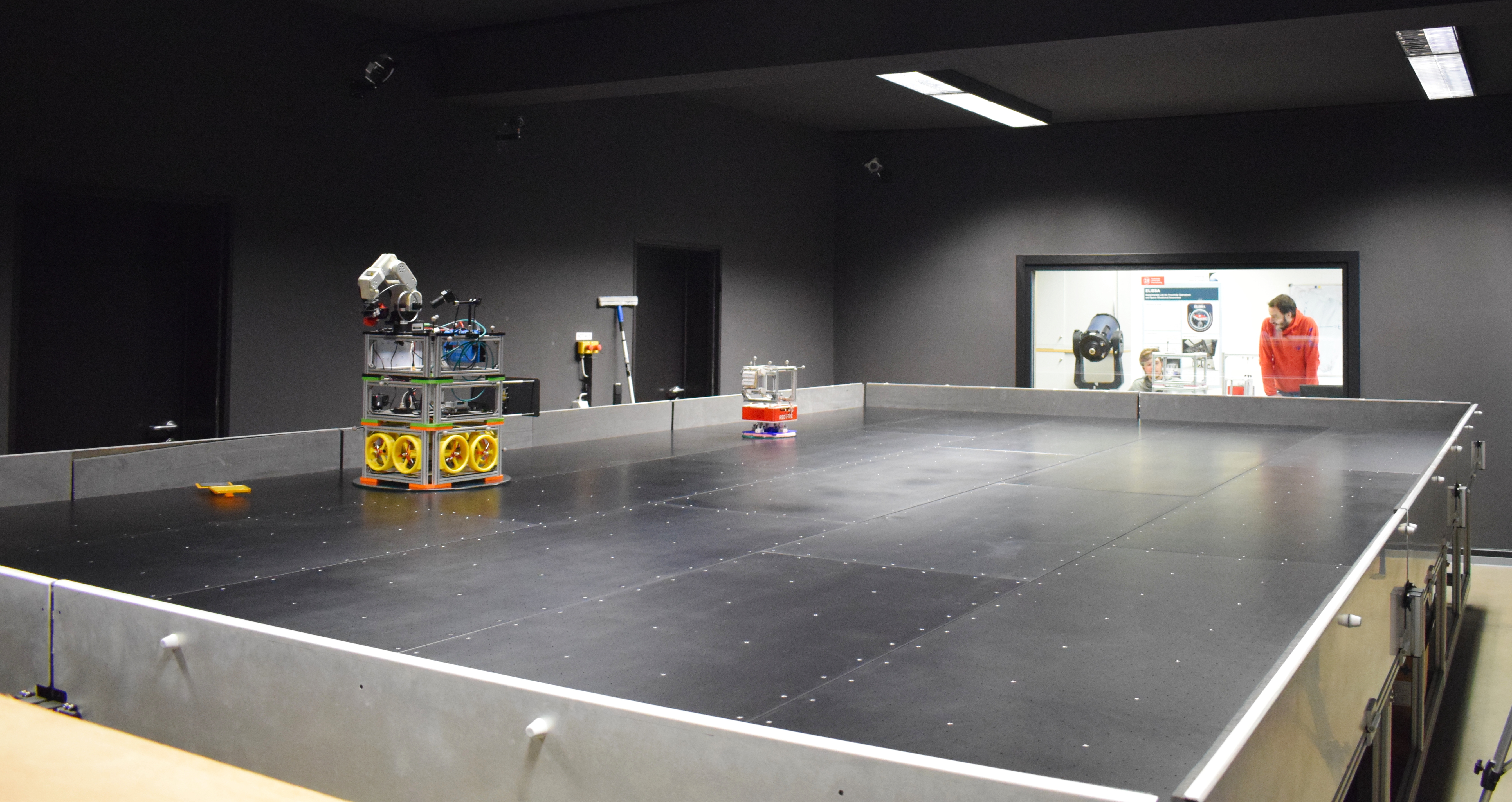
In the image above are two freeflyers shown. These are the satellite mockups operating on the table. They are described in detail in the next section. The position of the freeflyers is tracked using the motion tracking system. Multiple cameras are placed in the room overlooking the complete tested. These cameras detect the markers, which are placed on the freeflyers. In the tracking software, the corresponding markers are assigned to a freeflyer to get its position.
This is happening in the fourth subsystem, the mission control subsystem. The control room is visible in the picture above behind the glass window. At least two computers are used to run the software necessary for the laboratory operations. Windows is running on the first computer to run the following programs:
- INVERTER to control the blowers
- Motive to use the motion tracking system
An instruction on how to use the software is given in the Tutorial section of the wiki. The other computer is running Ubuntu 20.04 to provide the ROS infrastructure. Most of the necessary code to control the freeflyers and run mission specific code is executed on this machine.
Freeflyer Classes
The freeflyers are the satellite mockups operating on the ELISSA table. As real satellites, the freeflyers need different subsystems to function. The general systems are very similar between the different flyers. They all have:
- Propulsion module
- Service module
Furthermore each freeflyer can use mission specific payloads. The concrete details of each module differ depending on the freeflyer class. At the moment two freeflyer classes are used on the ELISSA testbed:
- Hannibal class freeflyers:
- Hannibal
- Pegasus
- Galactica
- Hamilcar class freeflyers:
- Hamilcar
- Red Five
- Ishimura (Exhibition Model)
- Moonraker (in construction)
Detail information about the freeflyers are provided on the linked pages. Each freeflyer has eight propellers to move it on the testbed. They are controlled by the Motor Control Unit (MCMU), which receives the commands from a corresponding node on the on-board computer of the freeflyer. This computer is connected to the mission control computer via a wireless network. It is integrated in the same ROS network and receives the commands from the Force Allocation Module (FAM). An overview of the ROS relations is given on the ROS architecture page. The different possible payloads are related to the experiment types, which are described in the following section.
Simulation Environment
The simulation environment used for ELISSA comes with the used ROS framework. It applies the same software structure described in detail here. Only the nodes interacting with the hardware components need to be replaced ot interact with the simulation instead.
The backbone of the physical simulation is Gazebo. Here, the different freeflyers as well as the table are simulated. The movement of the freeflyer is computed using the provided force goals for the propulsion motors. The freeflyers can interact (mostly collide) with the table wall. A detailed mode of the table top is not given. So it is not possible for the freeflyer to get stuck on the panel borders.
While Gazebo is simulating the robot, the RViz module (short for ROS visualization) is visualizing the position, orientation and state of the robot. It does not conduct any simulation, but instead shows the operator the situation the robot is in. Therefore, RViz is used in the simulation as well as the laboratory environment. It takes the state of the robot, either by Gazebo or the motion tracking system, and presents the data in the corresponding window.
Experiment Types
The main aim of ELISSA is to conduct hardware in the loop experiments. Depending on the current research, different experiment types are possible. Currently, mostly docking and printing experiments are conducted.
The purpose of the docking experiments is the research on Active Debris Removal (ADR). Here, a chaser satellite tries to dock to a (normally) uncooperative target to remove it from its orbit. This target may move in an uncontrolled and unknown way. Therefore it is necessary to monitor the movement from the chasers perspective to get a valid state of the target satellite. If the movement is known, a trajectory is calculated and the chaser moves to intercept and dock with the target satellite. To support this research, multiple other experiments are done, like measuring the docking forces or trying different materials for the passive docking. Furthermore, the research can be extended to on-orbit servicing and other fields. An instruction how to run the experiments is given in the user guides section.
The printing experiments focus on the research for on-orbit manufacturing. Currently, the Hannibal freeflyer is equipped with a robotic arm. At the end of the arm is a 3D printing head. Using this, different experiments are conducted on printing with this arm and an active freeflyer. Therefore, a table is placed on the ELISSA testbed functioning as the printing bed. Here, different structures can be printed, like a truss. Experiments with different materials like PLA supported by carbon fibers are conducted as well.
Package Structure
tbd