Optitrack
The Optitrack system captures the position of the freeflyers.
Table of Content:
Recalibrating Optritrack
This guide provides a step by step description of the process required to recalibrate the Optritrack system.
See this site as a reference.
- Remove all objects with reflectors from the table and make sure none are visible from the control center.
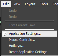
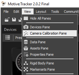
- Reset the application settings (Edit > Reset Application Settings).
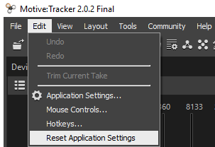
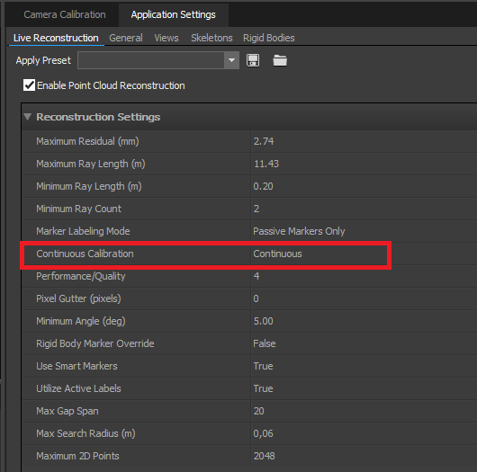
- Then go to “Application Settings” pane and set the “Continuous Calibration” setting as “Continuous”.
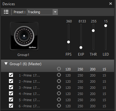
- Set a small FPS for calibration, EXP 250, THR 200, LED 15.
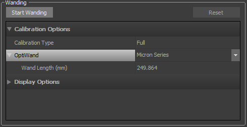
- In the Camera Calibration Pane, set the OptiWand in the Calibration Options as Micron Series, and the Wand Length(mm) is set as 249.864 for our calibration device.
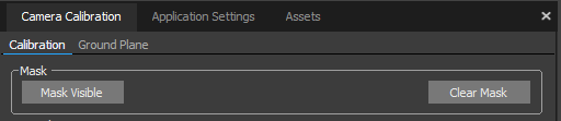
- Click the button “Clear Mask”, then click the button “Mask Visible”.
- Click the button “Start Wanding” and start wanding until all cameras show a green calibration status on their rim using the OptiWand.
- Calculate the calibration quality when sufficient data is obtained.
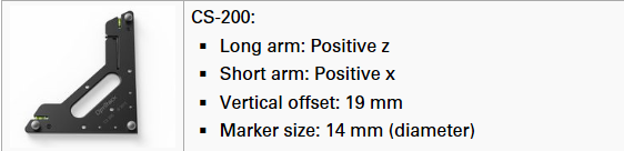
- Set the vertical offset of the calibration square (CS-200) for our motion capture system to 19 mm. Press the button “Set Ground Pane”.
Visit this site for further information on calibration squares. - In new calibration: View – Data Streaming Pane
- Activate “Broadcast Frame Data”,
- Activate “Broadcast VRPN Data”
- Set the Up axis to “Z up”
- Redefine rigid bodies:
- mark the reflectors at the upper 4 corners of an object
- select: right click - rigid body - create from selected markers
- rename the object: bsp.: vrpn/hannibal
- add all remaining reflectors of the object to the rigid body by marking them together with the already defined ones